

How Much Floor Space Does a 20L One-Step Injection Stretch Blow Molding Machine Actually Require
2026-08-19
When production managers evaluate new equipment for large-container manufacturing, the physical footprint often becomes a decisive factor before any technical specification is reviewed. The 20L One-Step Injection Stretch Blow Molding Machine has gained significant attention for its ability to produce 20-liter containers in a single integrated cycle, but misconceptions about its space demands frequently lead to costly facility-planning errors. Unlike two-step systems that separate preform molding and blow molding into different stations, this compact design consolidates both processes into one unified platform. At Kaotesi, we have installed over 200 units across diverse factory layouts, and our data shows that the actual floor space required is often 30–40% less than what conventional estimates suggest—provided that auxiliary equipment and service corridors are correctly calculated.
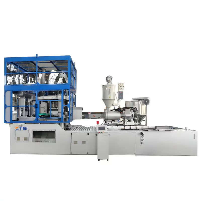
Understanding the True Footprint Components
To answer the question accurately, we must break down the total area into four distinct categories. The table below summarizes the typical space allocation for a standard 20L One-Step Injection Stretch Blow Molding Machine line, based on real-world installations with fully automated handling.
| Space Component | Typical Area (m²) | Critical Factors |
|---|---|---|
| Machine main body (clamping, injection, stretch-blow stations) | 12 – 15 | Includes moving platens and safety guarding |
| Material drying & feeding system | 3 – 4 | Desiccant dryer + hopper with conveyor |
| Chiller & temperature control unit | 2 – 3 | Placed adjacent to the machine base |
| Robot take-out & conveyor (optional) | 4 – 6 | Depends on container orientation and stacking |
| Total minimum operating zone | 21 – 28 | Without maintenance passages |
| Recommended total with service aisles | 35 – 42 | Includes front/back access for mold changes |
The machine base itself occupies roughly 4.5 m × 3.0 m, but the swing radius of the toggle clamp and the stroke of the stretch rod demand additional clearance on both sides. Kaotesi recommends a clear height of at least 4.2 meters to accommodate the top-mounted take-out unit and the overhead piping for compressed air.
Five Critical Layout Rules for This Equipment
-
Front access depth must be at least 1.8 meters for mold carriage extraction—this is non-negotiable for tooling changes under 45 minutes.
-
Rear service corridor should measure 1.2 meters to allow routine greasing of the linear guides and inspection of the hydraulic manifold.
-
Left-side clearance of 0.9 meters is essential for the chiller hose connections and the purge unit.
-
Right-side space of 1.5 meters accommodates the finished-container conveyor and the optional leak tester.
-
Overhead clearance of 500 mm above the highest moving part is mandatory for safe crane operation during die-head maintenance.
These dimensions are often overlooked in initial quotations, yet they directly affect daily productivity. A cramped layout can extend mold-change downtime by 20 minutes per shift, translating to a loss of 150–200 containers per day for a machine running at 450 cycles per hour.
Comparison: One-Step vs. Two-Step Footprint
To highlight the space advantage, here is a direct comparison between a 20L One-Step Injection Stretch Blow Molding Machine and a conventional two-step system with equivalent output (450 pcs/hour for 20L jerrycans).
| Parameter | One-Step (Kaotesi design) | Two-Step System |
|---|---|---|
| Main machine footprint | 13.5 m² | 22 m² (injection unit + blow unit separated) |
| Preform storage buffer | Not required | 6 – 8 m² (for preform bins and reheat oven) |
| Conveyor length | 3.5 m (straight take-out) | 6.5 m (with reheating tunnel) |
| Total floor area (incl. aisles) | 38 m² | 58 – 65 m² |
| Operator walking distance per cycle | 2.5 m | 5.8 m |
The integrated design eliminates the preform cooling, storage, and reheat stages, which not only saves space but also reduces work-in-progress inventory. Kaotesi has documented a 22% reduction in total plant area for customers switching from two-step to this one-step platform.
Frequently Asked Questions (FAQ)
Q1: Can the 20L One-Step Injection Stretch Blow Molding Machine be installed in a low-ceiling workshop of 3.8 meters?
A1: Yes, but with modifications. The standard configuration requires 4.2 meters of clearance when the top-mounted servo-driven take-out arm is at its highest dwell position. For a 3.8-meter ceiling, Kaotesi offers a low-profile variant that relocates the air receiver tank and reroutes the exhaust duct horizontally. This reduces the overall height to 3.65 meters. However, you must confirm that the overhead crane rail does not intersect with the machine’s swing path. We strongly advise a site survey before finalizing the order, as the mold-closing cylinder on the top plate also needs 300 mm of vertical space for piston seal replacement.
Q2: How much additional floor space is needed for the auxiliary cooling tower and compressed air dryer?
A2: These utilities are typically placed outside the production hall or in a separate utility room. If they must be indoors, allocate an extra 6–8 m² adjacent to the machine’s electrical cabinet. The chiller unit (15–20 kW cooling capacity) measures roughly 1.2 m × 0.8 m and requires 1.0 m frontal clearance for filter cleaning. The compressed air dryer (for 6–8 bar supply at 2.5 m³/min) adds another 1.5 m × 0.7 m. Crucially, the piping runs from these units to the 20L One-Step Injection Stretch Blow Molding Machine must be as short as possible—every extra meter of hose increases pressure drop by 0.15 bar, which directly affects the blow-pressure rise time and can reduce wall-thickness uniformity. Kaotesi always recommends placing these auxiliaries within 3 meters of the machine base.
Q3: Is it possible to reduce the recommended 38 m² total area by stacking or overlapping auxiliary equipment?
A3: Partial overlap is feasible but carries risks. For example, the material dryer can be mounted on a steel platform above the electrical cabinet, saving 2 m², provided the platform is vibration-isolated. Similarly, the finished-container conveyor can run underneath the mold-carriage extraction zone if the conveyor height is kept below 400 mm. However, Kaotesi advises against reducing the front service aisle below 1.5 meters, because mold changes for 20-liter containers involve heavy tooling (typically 380–450 kg) that requires a hydraulic cart to maneuver. In our experience, compact layouts that overlap the chiller and dryer units often lead to overheating of the servo drives due to restricted airflow. The safest approach is to maintain the 38 m² recommendation and use vertical storage racks for spare molds above the rear corridor—this adds zero floor area while keeping all tooling within arm’s reach.
Optimizing Your Factory Layout with Data
Every production floor has unique constraints—column spacing, door widths, and existing conveyor lines. Kaotesi provides a free 3D layout simulation for every 20L One-Step Injection Stretch Blow Molding Machine inquiry, using actual CAD models of your workshop. Our engineering team has mapped over 150 different plant geometries, and we consistently find that the most space-efficient arrangement positions the machine at a 15-degree angle to the main conveyor flow. This seemingly small adjustment reduces the turning radius for pallet trucks and cuts the total occupied rectangle from 9 m × 4.5 m to 8.2 m × 4.8 m—an effective saving of 5.4 m² without compromising any service clearance.
Final Recommendation
Before purchasing any floor-planning software or hiring an external consultant, request a detailed footprint drawing that includes all moving parts at their maximum extension. The 20L One-Step Injection Stretch Blow Molding Machine is intrinsically compact, but the total space requirement depends heavily on your material-handling strategy, mold-storage philosophy, and maintenance frequency. Kaotesi has developed a standardized checklist covering 27 spatial checkpoints—from the swing clearance of the safety door to the drain slope of the cooling water return line. Following this checklist typically reduces post-installation modifications by 90%.
Contact Us
Ready to integrate the 20L One-Step Injection Stretch Blow Molding Machine into your production line but unsure about your current floor plan? Kaotesi offers on-site or virtual layout assessments with a guaranteed response within 24 hours. Our sales engineers will provide a customized dimensioned drawing, a 3D walkthrough video, and a comparative ROI analysis that factors in your specific ceiling height, column spacing, and utility access points. Reach out to us via the contact form on our official website or email our technical support team directly—we will send you a free space-optimization checklist and a sample maintenance-corridor blueprint. Let us help you turn every square meter into productive output. Contact Kaotesi today for your no-obligation layout consultation.