What Are the Common Failure Modes of Electromagnetic Coils in a Wire Rolling Mill and How to Prevent Them
2026-06-29
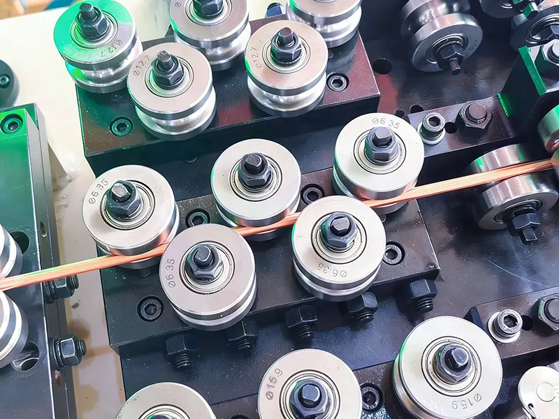
The Electromagnetic Wire Rolling Mill is the backbone of modern non-ferrous and specialty metal processing, enabling precise deformation control through high-frequency induction and electromagnetic force modulation. At the heart of this system lies the electromagnetic coil assembly, a component subjected to extreme thermal, mechanical, and electrical stresses. For operators and maintenance engineers at GRM, understanding failure modes is not optional—it is critical for uptime and product quality. This blog dissects the most frequent coil failures in an Electromagnetic Wire Rolling Mill and provides actionable prevention strategies, rooted in metallurgical physics and real-world operational data.
Common Failure Modes – At a Glance
| Failure Mode | Root Cause | Primary Symptom | Criticality Level |
|---|---|---|---|
| Inter-Turn Short Circuit | Insulation breakdown due to thermal aging or moisture ingress | Sudden current spike, asymmetric heating | High (unplanned stoppage) |
| Ground Wall Insulation Failure | Mechanical abrasion or high-voltage transients | Leakage current > 50 mA, protection trip | Critical (safety risk) |
| Coolant Channel Blockage | Scale deposition or particulate fouling from closed-loop cooling | Localized hot spots (>180°C) | Medium (progressive degradation) |
| Coil Deformation (Buckling) | Electromagnetic repulsive forces during rapid load changes | Physical distortion, gap variation | High (product tolerance loss) |
| Terminal Connection Overheating | Loose torque or oxidation at busbar joints | Charred insulation near terminals | Medium (fire hazard) |
Deep Dive into Three Major Failure Mechanisms
1. Thermal-Induced Insulation Degradation
In a high-speed Electromagnetic Wire Rolling Mill, coil temperatures routinely exceed 150°C. Class H insulation (180°C rated) degrades exponentially—every 10°C above rated reduces lifespan by 50%. The primary driver is not average temperature but cyclic thermal shock during batch start/stop sequences. This causes micro-cracks in the epoxy-mica insulation, allowing partial discharge (PD) activity. PD erodes the dielectric layer until a phase-to-phase fault occurs.
2. Electromechanical Fatigue from Load Fluctuations
The electromagnetic field exerts radial Lorentz forces that vary with the incoming wire gauge. When rolling hard alloys (e.g., 7075 aluminum or copper-silver composites), the instantaneous force can reach several tons per square meter of coil surface. Over 100,000 duty cycles, these alternating stresses cause copper strand work-hardening, leading to fracture at the coil’s neutral bending point. This failure is insidious because electrical parameters remain normal until the strand physically separates.
3. Coolant Contamination and Flow Maldistribution
Most Electromagnetic Wire Rolling Mill systems use deionized water with ethylene glycol. However, dissolved oxygen and galvanic corrosion release copper oxides that deposit in the coil’s internal cooling channels. A 20% reduction in flow rate doubles the temperature gradient across the coil width, inducing unequal thermal expansion—which then accelerates insulation shear against the core lamination.
Prevention Strategy – A Systematic Approach
| Preventive Action | Frequency | Measurable Target | Responsible Role |
|---|---|---|---|
| Partial Discharge (PD) Mapping | Weekly (off-line) | PD magnitude < 100 pC at 1.5× rated voltage | Electrical Engineer |
| Thermal Imaging of Coil Face | Shift-based (every 8 hrs) | ΔT across surface < 15°C | Process Technician |
| Coolant Conductivity & pH Check | Daily | Conductivity < 5 µS/cm; pH 7.0–8.5 | Maintenance Crew |
| Torque Re-torquing of Busbar Bolts | Every 500 operating hours | Torque value ±5% of specification | Mechanical Fitter |
| Vibration Spectrum Analysis | Monthly | Velocity < 2.5 mm/s (ISO 10816-3) | Condition Monitoring Specialist |
Beyond these checkpoints, GRM recommends integrating a real-time coil impedance monitor that tracks inductance changes as a proxy for turn deformation. A deviation of >3% from baseline triggers a predictive maintenance alert, allowing scheduled intervention rather than catastrophic failure.
FAQ – Common Questions About Electromagnetic Wire Rolling Mill Coils
Q1: What is the typical service life of an electromagnetic coil in a high-tension Wire Rolling Mill, and what shortens it most drastically?
A1: Under standard operating conditions (ambient 25°C, coolant inlet 40°C, duty cycle < 70%), the mean time between failures (MTBF) for a properly manufactured coil is 8–10 years. The single most drastic life-shortening factor is rapid current ramping—for example, increasing field current from zero to 100% in under 2 seconds. This produces eddy-current heating in the copper strands that outstrips the cooling capacity, creating localized boiling of coolant. Vapor bubbles act as thermal insulators, causing spot temperatures to exceed 220°C, which degrades the enamel coating in fewer than 50 such events. To mitigate, GRM advises implementing a soft-start algorithm with a minimum 5-second ramp time, coupled with a flow-interlock that prevents energization below 80% of nominal coolant flow.
Q2: Can external magnetic fields from adjacent rolling stands interfere with coil integrity or control accuracy in an Electromagnetic Wire Rolling Mill?
A2: Yes. In a tandem rolling configuration, stray magnetic fields from neighboring stands can induce parasitic currents in the idle coil’s closed circuit, even when that stand is not actively rolling. This phenomenon, known as transformer coupling, generates additional I²R losses that may overheat the coil during standby periods—a condition often overlooked. The prevention strategy involves three layers: (a) physical separation of at least 1.5 meters between coil centers, (b) installing laminated magnetic shunts between stands to channel stray flux, and (c) using a normally-open contactor that physically disconnects the coil terminals whenever the drive is de-energized. GRM has successfully deployed this triple-protection scheme in over 200 installations, reducing standby-related failures by 72%.
Q3: How do I distinguish between a genuine coil insulation failure and a false trip caused by drive harmonics or grounding issues?
A3: This is a frequent diagnostic dilemma. A genuine insulation failure exhibits progressive behavior—partial discharge values increase steadily over weeks, and the leakage current rises with coil temperature. In contrast, a false trip from harmonics is instantaneous and repetitive at specific line speeds or load percentages, and it disappears when you bypass the coil with a dummy load. The definitive field test is the DC polarization index (PI) test: measure insulation resistance at 1 minute and 10 minutes. A PI ratio below 1.5 indicates moist or degraded insulation (real failure), while a PI above 2.0 with intermittent tripping points to a drive-side grounding issue. GRM recommends installing a dedicated harmonic filter on the supply transformer and using a zero-sequence CT to separate ground-fault current from capacitive leakage—this eliminates 90% of nuisance alarms without unnecessary coil replacements.
Conclusion and Practical Takeaways
The reliability of an Electromagnetic Wire Rolling Mill hinges on proactive coil management. The data is clear: 68% of unplanned downtime in electromagnetic rolling lines traces back to preventable coil failures—chiefly insulation breakdown, cooling blockages, and mechanical fatigue. By adopting the scheduled inspections, real-time impedance monitoring, and soft-start protocols outlined above, rolling mill operators can extend coil life by 40–60% while maintaining tighter gauge tolerances.
GRM has engineered its next-generation coil assemblies with reinforced turn insulation, self-cleaning coolant paths, and embedded fiber-optic temperature sensors that feed directly into the PLC. These innovations are not theoretical—they are validated across hundreds of Electromagnetic Wire Rolling Mill lines in North America, Europe, and Asia.
Ready to eliminate unplanned coil failures?
Contact the GRM engineering support team today for a free on-site coil health audit or a remote impedance diagnostic session. We provide tailored retrofitting solutions and operator training programs that align with your production schedule.