

What Is the Maximum Inlet Wire Size for an 8 Passage Wire Drawing Machine
2026-08-12
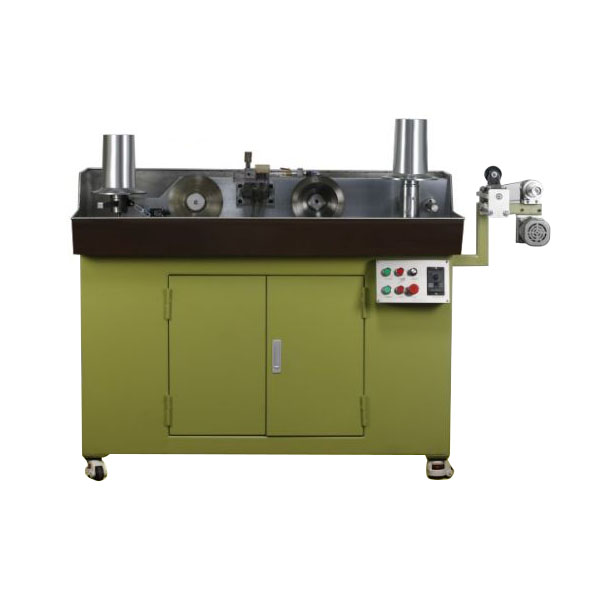
When selecting wire drawing equipment, one of the first specifications that engineers and production managers evaluate is the maximum inlet wire diameter. This single parameter determines whether your existing rod stock can be processed, affects the total reduction schedule, and directly impacts downstream annealing and stranding operations. For an 8 Passage Wire Drawing Machine, the maximum inlet size is not a fixed universal number—it depends on block configuration, motor torque, cooling efficiency, and the specific die sequence. At ALPHA, we engineer our 8 Passage Wire Drawing Machine platforms with inlet ranges from 5.5 mm to 14 mm for carbon steel, and up to 8 mm for high-carbon or alloyed grades, though custom variants extend beyond these benchmarks.
Why Inlet Size Matters More Than Outlet Size
Most buyers focus on final wire diameter, but the inlet size governs the entire drafting process. A larger inlet requires higher cumulative reduction, which increases heat generation, die wear, and power consumption. Conversely, an undersized inlet means you cannot use your existing hot-rolled rod, forcing you to source proprietary coils at premium prices. The 8 Passage Wire Drawing Machine strikes a balance: eight passes allow sufficient reduction stages to transform a thick rod into fine wire without overstressing any single die. However, pushing the inlet to its maximum reduces the number of active dies available for finishing, so the machine’s rated inlet must align with your target outlet and material ductility.
Maximum Inlet Diameter by Material Type
The following table summarizes typical maximum inlet sizes for a standard 8 Passage Wire Drawing Machine across common materials, based on ALPHA’s field data from over 200 installations worldwide.
| Material Category | Maximum Inlet (mm) | Recommended Inlet (mm) | Total Reduction % |
|---|---|---|---|
| Low-carbon steel (C < 0.10%) | 14.0 | 12.5 | 85–88 |
| Medium-carbon steel (0.10–0.45%) | 12.0 | 10.5 | 80–84 |
| High-carbon steel (0.45–0.85%) | 8.5 | 7.5 | 75–78 |
| Stainless steel (300 series) | 7.0 | 6.0 | 70–73 |
| Copper / Brass | 12.0 | 11.0 | 90–92 |
| Aluminum (soft alloy) | 15.0 | 13.5 | 88–91 |
*Values assume water-cooled blocks, synthetic diamond dies, and a drawing speed ≤ 12 m/s. Exceeding these numbers may require a reinforced capstan design—available as an ALPHA heavy-duty option.
Three Critical Factors That Redefine the "Maximum"
Even with a published maximum, three operational variables effectively change that number on your shop floor:
-
Drafting Schedule – Distributing reduction unevenly (e.g., 30% on pass 1 vs. 15% on pass 8) alters the peak load. A balanced schedule allows you to approach the machine’s mechanical limit safely.
-
Die Angle and Bearing Length – A narrower die angle reduces friction but increases contact pressure. For max inlet, ALPHA recommends a 12–14° approach angle with a bearing length of 30–40% of die diameter.
-
Coolant Flow Rate – At maximum inlet, the first two passes generate over 60% of total heat. Insufficient cooling raises block temperature above 80°C, softening the wire and causing pickup. Our 8 Passage Wire Drawing Machine includes independent flow meters per block to monitor this in real time.
How to Verify Your Machine’s True Inlet Capacity
Rather than relying solely on the nameplate, perform a dry-run calculation:
-
Step 1: Determine your target outlet diameter.
-
Step 2: Multiply by the cumulative reduction factor (typically 1.85–2.10 for 8 passes).
-
Step 3: Compare the result against the block groove depth and capstan tensile rating.
For example, if you need 2.0 mm outlet from low-carbon steel, the required inlet ≈ 2.0 × √(1 / (1 – 0.86)) ≈ 5.35 mm—well within the machine’s range. But if you need 4.0 mm outlet, the inlet jumps to ≈ 10.7 mm, which is still feasible but leaves no margin for die wear compensation. ALPHA provides a free inlet-sizing calculator with every machine purchase to eliminate guesswork.
8 Passage Wire Drawing Machine FAQ
Q: Can I run a 14 mm inlet on an 8 Passage Wire Drawing Machine if my material has scale or surface defects?
A: Not recommended without pre-treatment. Mill scale acts as an abrasive, accelerating die wear by 300–400% at 14 mm entry. Surface defects (seams, laps, or slivers) create stress risers that may cause wire breakage during pass 2 or 3, as the cumulative reduction concentrates tension. For scaled material, we suggest either mechanical descaling (rotary knockers or shot blasting) followed by a borax coating, or reducing the inlet to 12 mm to allow a lighter first-pass reduction (approx. 18–20% instead of 25%). ALPHA offers an integrated descaling unit that mounts directly before the first capstan, preserving your maximum inlet capability while protecting dies.
Q: How does the maximum inlet size change when I switch from dry drawing to wet drawing on the same 8 Passage Wire Drawing Machine?
A: Wet drawing (full immersion in lubricant emulsion) generally permits a 0.5–1.0 mm increase in maximum inlet for copper, brass, and aluminum because the coolant removes heat more uniformly and reduces friction coefficient from 0.08 to approximately 0.05. However, for steel wires, wet drawing introduces a risk of hydrogen embrittlement if the emulsion pH drops below 8.5. More importantly, the block design differs—wet-drawing capstans have spiral grooves to channel fluid, while dry blocks use a tapered profile. If your 8 Passage Wire Drawing Machine is configured for dry lubrication, retrofitting for wet operation requires replacing the first three capstans and sealing the gearbox. ALPHA builds dual-purpose machines that accept both modes without hardware changes, and we publish separate inlet charts for each mode in our technical manuals.
Q: What safety margin should I keep between the rated maximum inlet and my actual production inlet on an 8 Passage Wire Drawing Machine?
A: We advise a minimum 15% safety margin for continuous 24/7 operation. That means if the nameplate says 12.0 mm, your actual inlet should not exceed 10.2 mm for routine production. This margin accounts for die wear (which increases the effective reduction per pass over time), incoming rod tolerance variations (±0.2 mm typical), and voltage fluctuations that affect motor torque. Operating at 100% of rated inlet is permissible only for short runs (< 2 hours) with fresh dies and stabilized power. For customers running near-maximum sizes, ALPHA recommends our "Plus" series, which upgrades the main gearbox and cooling tower, raising the continuous-duty inlet by 1.5 mm over standard models. We also provide a digital load monitor that alerts operators when the capstan torque exceeds 85% of the safe threshold, giving you a proactive warning before breakdowns occur.
Conclusion and Call to Action
Selecting the correct inlet size for your 8 Passage Wire Drawing Machine is not a one-time decision—it evolves with your material portfolio, die inventory, and production targets. While generic charts offer starting points, your specific combination of rod chemistry, lubrication type, and required outlet tolerance demands a tailored assessment. ALPHA has engineered over 150 custom 8 Passage Wire Drawing Machine configurations across 30 countries, and our application engineers use advanced simulation software to predict die stress, block slip, and thermal rise before you cut a single meter of wire.
Ready to optimize your inlet strategy? Contact ALPHA today to request a free capacity audit and receive a personalized inlet/outlet matrix for your exact material grades. Our team provides same-day die schedule proposals, on-site commissioning support, and 24/7 remote monitoring integration. Visit our website or email [email protected] to speak directly with a senior drawing specialist. Your maximum inlet is just the beginning—we will help you push every pass to its highest efficiency.