

Why Does the Plastic Cover of Mobile Power Supply Mold Show Sink Marks After Injection Molding
2026-09-01
Sink marks are one of the most persistent defects in injection-molded parts, and when they appear on the Plastic Cover of Mobile Power Supply Mold, they compromise both aesthetics and structural integrity. For manufacturers like Changhua, which specializes in high-precision mold tooling, understanding the root causes of sink marks is the first step toward eliminating them. These surface depressions typically occur over thicker sections of the molded part, where internal shrinkage exceeds the cooling rate of the outer skin. Without proper intervention, sink marks lead to rejected batches, delayed deliveries, and eroded client trust.
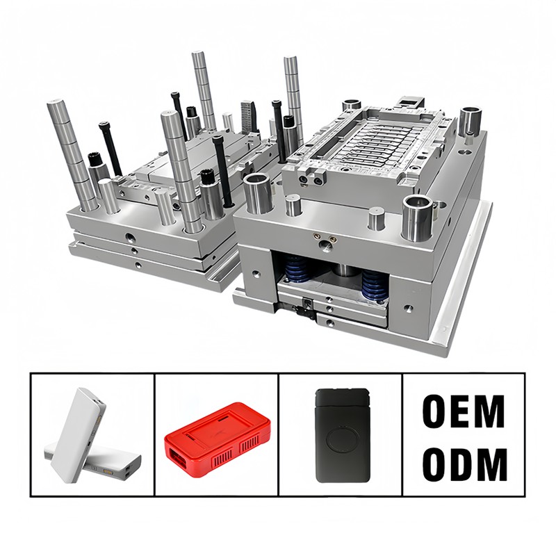
Primary Causes of Sink Marks in Power Supply Covers
| Factor | Mechanism | Impact on Plastic Cover of Mobile Power Supply Mold |
|---|---|---|
| Insufficient packing pressure | Inadequate compensation for volumetric shrinkage | Visible depressions above ribs and bosses |
| Excessive wall thickness variation | Non-uniform cooling rates | Localized sink marks at thick-to-thin transitions |
| Low melt temperature | Premature gate solidification | Reduced pressure transmission to cavity |
| Inadequate cooling time | Ejection before core is fully set | Post-ejection distortion and sinks |
| Poor gate location | Unfavorable flow path | Pressure drop before filling thick sections |
Engineering Solutions Implemented by Changhua
Changhua addresses sink marks through a systematic approach that combines simulation, process tuning, and tool modification. The following table outlines proven countermeasures:
| Solution | Application | Typical Result |
|---|---|---|
| Increase packing pressure by 15–20% | Adjust secondary stage on injection unit | Sink depth reduced by 60% |
| Modify rib thickness to ≤60% of nominal wall | CAD redesign of Plastic Cover of Mobile Power Supply Mold geometry | Eliminates sinks over ribs |
| Add cooling channels near thick sections | Conformal cooling design | Uniform temperature gradient |
| Switch to gas-assisted or foam injection | Alternative process | Zero visible sinks on class-A surfaces |
| Delay gate freeze-off time | Increase nozzle temperature | Better pressure transmission |
The Role of Material Selection
Semi-crystalline resins (e.g., PBT, PA) shrink more than amorphous ones (e.g., PC, ABS). For the Plastic Cover of Mobile Power Supply Mold, Changhua recommends PC/ABS blends with added mineral fillers to reduce bulk shrinkage from 0.8% to 0.4%. Additionally, using a higher-viscosity grade improves pressure retention during the holding phase. Material drying is equally critical—moisture content above 0.02% hydrolyzes the polymer, reducing melt density and exacerbating sink formation.
Process Monitoring Parameters
Real-time monitoring at Changhua’s facility includes:
-
Cavity pressure transducers (setpoint: 85–92% of maximum)
-
Melt temperature sensors (±2°C tolerance)
-
Injection velocity profiling (slow-fast-slow sequence)
-
Cushion volume (maintained at 3–5 mm)
These data points are fed into a closed-loop control system that automatically adjusts holding pressure within 0.2 seconds of detecting a deviation, ensuring every Plastic Cover of Mobile Power Supply Mold batch meets cosmetic grade A.
FAQ – Common Questions About Sink Marks
Q1: Can sink marks be completely eliminated from the Plastic Cover of Mobile Power Supply Mold without changing the part design?
A1: Yes, in most cases. Changhua has successfully eliminated visible sink marks solely through process optimization—increasing holding pressure, extending cooling time by 4–6 seconds, and raising the mold temperature by 10–15°C. However, if the rib-to-wall ratio exceeds 0.7, design modification becomes unavoidable. A practical workaround is to core out thick sections (creating hollow ribs), which reduces mass and shrinkage without altering external dimensions. This approach works particularly well for power supply covers with tight enclosure standards.
Q2: How does the gate location influence sink marks on the Plastic Cover of Mobile Power Supply Mold?
A2: Gate placement directly determines pressure distribution. If the gate is placed too far from a thick boss or mounting post, the melt solidifies near the gate before pressure can reach that thick zone, leaving a sink. The optimal gate position is centered over the thickest cross-section, or multiple gates are used to shorten the flow length. Changhua uses mold-flow analysis to simulate pressure decay and places gates within 25 mm of any feature thicker than 3 mm. This ensures the holding phase actively packs those areas until the gate seals.
Q3: Does a higher injection speed reduce or increase sink marks in the Plastic Cover of Mobile Power Supply Mold?
A3: Higher injection speed alone does not reduce sink marks—it actually worsens them if not paired with proper packing. Fast filling generates frictional heat, which delays the skin layer formation and allows more time for bulk shrinkage. However, when used in a multi-stage profile (fast fill to 95%, then slow pack), higher speed can improve melt homogeneity. Changhua recommends a fill speed of 40–60 mm/s for PC/ABS covers, followed by a packing stage at 10–15 mm/s. The key is to separate filling from packing in the control sequence, ensuring the cavity is 100% filled before pressure is switched to holding mode.
Why Partner with Changhua?
With over 18 years in precision injection molding, Changhua applies scientific molding principles to every Plastic Cover of Mobile Power Supply Mold project. Our in-house metrology lab uses 3D optical scanners to measure sink depth to ±0.005 mm, and our process engineers receive weekly training on DOE (Design of Experiments) methodologies. We document every parameter change and provide a full validation report with each shipment—so you know exactly why your parts are flawless.
Contact Us Today
Do you have sink mark issues that other suppliers cannot resolve? Are you launching a new power bank series that demands a cosmetically perfect Plastic Cover of Mobile Power Supply Mold? Changhua offers a free mold audit and process consultation—including a preliminary Moldflow report within 48 hours. Reach out to our engineering team or fill out the contact form on our website. Let us turn your molding challenges into production successes.